| NO | Ød | ØD | b | B | C | R1 |
|---|---|---|---|---|---|---|
| JP-20*12.5*3.2 HPS2 | 12.5 | 20 | 3 | 3.2 | 2 | 0.2 |
| JP-20*14*4.2 HPS2 | 14 | 20 | 4 | 4.2 | 2.5 | 0.3 |
| JP-25*17.5*3.2 HPS2 | 17.5 | 25 | 3 | 3.2 | 2 | 0.2 |
| JP-30*22.5*3.2 HPS2 | 22.5 | 30 | 3 | 3.2 | 2 | 0.2 |
| JP-32*21*4.2 HPS2 | 21 | 32 | 4 | 4.2 | 2.5 | 0.3 |
| JP-32*24.5*3.2 HPS2 | 24.5 | 32 | 3 | 3.2 | 2 | 0.2 |
| JP-40*27*6.3 HPS2 | 27 | 40 | 6 | 6.3 | 3 | 0.3 |
| JP-40*29*4.2 HPS2 | 29 | 40 | 4 | 4.2 | 2.5 | 0.3 |
| JP-40*32.5*3.2 HPS2 | 32.5 | 40 | 3 | 3.2 | 2 | 0.2 |
| JP-45*32*6.3 HPS2 | 32 | 45 | 6 | 6.3 | 3 | 0.3 |
| JP-45*34*4.2 HPS2 | 34 | 45 | 4 | 4.2 | 2.5 | 0.3 |
| JP-50.8*41.4*7.14 HPS2 | 41.4 | 50.8 | 6.85 | 7.14 | 4 | 0.3 |
| JP-50*34.5*6.3 HPS2 | 34.5 | 50 | 6 | 6.3 | 3 | 0.3 |
| JP-50*37*6.3 HPS2 | 37 | 50 | 6 | 6.3 | 3 | 0.3 |
| JP-50*39*4.2 HPS2 | 39 | 50 | 4 | 4.2 | 2.5 | 0.3 |
| JP-55*39.5*6.3 HPS2 | 39.5 | 55 | 6 | 6.3 | 3 | 0.3 |
| JP-60*44.5*6.3 HPS2 | 44.5 | 60 | 6 | 6.3 | 3 | 0.3 |
| JP-60*49*4.2 HPS2 | 49 | 60 | 4 | 4.2 | 2.5 | 0.3 |
| JP-63*47.5*6.3 HPS2 | 47.5 | 63 | 6 | 6.3 | 3 | 0.3 |
| JP-63*50*6.3 HPS2 | 50 | 63 | 6 | 6.3 | 3 | 0.3 |
| JP-63*52*4.2 HPS2 | 52 | 63 | 4 | 4.2 | 2.5 | 0.3 |
| JP-65*49.5*6.3 HPS2 | 49.5 | 65 | 6 | 6.3 | 3 | 0.3 |
| JP-65*52*6.3 HPS2 | 52 | 65 | 6 | 6.3 | 3 | 0.3 |
| JP-65*54*6.3 HPS2 | 54 | 65 | 6 | 6.3 | 4 | 0.3 |
| JP-70*54.5*6.3 HPS2 | 54.5 | 70 | 6 | 6.3 | 4 | 0.3 |
| JP-70*57*6.3 HPS2 | 57 | 70 | 6 | 6.3 | 4 | 0.3 |
| JP-70*59*4.2 HPS2 | 59 | 70 | 4 | 4.2 | 3 | 0.3 |
| JP-75*59.5*6.3 HPS2 | 59.5 | 75 | 6 | 6.3 | 4 | 0.3 |
| JP-75*62*6.3 HPS2 | 62 | 75 | 6 | 6.3 | 4 | 0.3 |
| JP-80*59*8.1 HPS2 | 59 | 80 | 7.75 | 8.1 | 5 | 0.4 |
| JP-80*59*10.5 HPS2 | 59 | 80 | 10 | 10.5 | 7 | 0.4 |
| JP-80*64.5*6.3 HPS2 | 64.5 | 80 | 6 | 6.3 | 4 | 0.3 |
| JP-80*66.5*6.3 HPS2 | 66.5 | 80 | 6 | 6.3 | 4 | 0.3 |
| JP-80*69*4.2 HPS2 | 69 | 80 | 4 | 4.2 | 3 | 0.3 |
| JP-85*69.5*6.3 HPS2 | 69.5 | 85 | 6 | 6.3 | 4 | 0.3 |
| JP-85*71.5*6.3 HPS2 | 71.5 | 85 | 6 | 6.3 | 4 | 0.3 |
| JP-90*69*8.1 HPS2 | 69 | 90 | 7.75 | 8.1 | 5 | 0.4 |
| JP-90*69*10.5 HPS2 | 69 | 90 | 10 | 10.5 | 7 | 0.4 |
| JP-90*74.5*6.3 HPS2 | 74.5 | 90 | 6 | 6.3 | 4 | 0.3 |
| JP-95*79.5*6.3 HPS2 | 79.5 | 95 | 6 | 6.3 | 4 | 0.3 |
| JP-100*79*8.1 HPS2 | 79 | 100 | 7.75 | 8.1 | 5 | 0.4 |
| JP-100*84.5*6.3 HPS2 | 84.5 | 100 | 6 | 6.3 | 4 | 0.3 |
| JP-100*86.5*6.3 HPS2 | 86.5 | 100 | 6 | 6.3 | 4 | 0.3 |
| JP-100*89.5*6.3 HPS2 | 89.5 | 100 | 6 | 6.3 | 4 | 0.3 |
| JP-101.6*92.2*7.14 HPS2 | 92.2 | 101.6 | 6.85 | 7.14 | 4 | 0.3 |
| JP-105*89.5*6.3 HPS2 | 89.5 | 105 | 6 | 6.3 | 4 | 0.3 |
| JP-110*89*8.1 HPS2 | 89 | 110 | 7.75 | 8.1 | 5 | 0.4 |
| JP-110*89*10.5 HPS2 | 89 | 110 | 10 | 10.5 | 7 | 0.4 |
| JP-110*94.5*6.3 HPS2 | 94.5 | 110 | 6 | 6.3 | 4 | 0.3 |
| JP-115*94*8.1 HPS2 | 94 | 115 | 7.75 | 8.1 | 5 | 0.4 |
| JP-120*99*8.1 HPS2 | 99 | 120 | 7.75 | 8.1 | 5 | 0.4 |
| JP-120*99*10.5 HPS2 | 99 | 120 | 10 | 10.5 | 7 | 0.4 |
| JP-120*104.5*6.3 HPS2 | 104.5 | 120 | 6 | 6.3 | 4 | 0.3 |
| JP-125*104*10.5 HPS2 | 104 | 125 | 10 | 10.5 | 7 | 0.4 |
| JP-125*104*8.1 HPS2 | 104 | 125 | 7.75 | 8.1 | 5 | 0.4 |
| JP-125*109.5*6.3 HPS2 | 109.5 | 125 | 6 | 6.3 | 4 | 0.3 |
| JP-130*109*8.1 HPS2 | 109 | 130 | 7.75 | 8.1 | 5 | 0.4 |
| JP-140*119*8.1 HPS2 | 119 | 140 | 7.75 | 8.1 | 5 | 0.4 |
| JP-140*119*10.5 HPS2 | 119 | 140 | 10 | 10.5 | 7 | 0.4 |
| JP-150*129*8.1 HPS2 | 129 | 150 | 7.75 | 8.1 | 5 | 0.4 |
| JP-150*129*10.5 HPS2 | 129 | 150 | 10 | 10.5 | 7 | 0.4 |
| JP-160*139*8.1 HPS2 | 139 | 160 | 7.75 | 8.1 | 5 | 0.4 |
| JP-180*159*8.1 HPS2 | 159 | 180 | 7.75 | 8.1 | 5 | 0.4 |
| JP-200*175*12.5 HPS2 | 175 | 200 | 12 | 12.5 | 9 | 0.4 |
| JP-200*179*8.1 HPS2 | 179 | 200 | 7.75 | 8.1 | 5 | 0.4 |
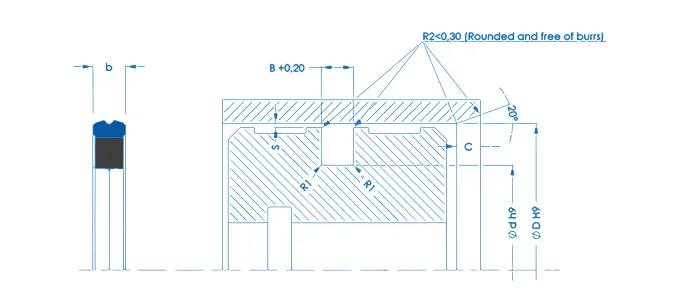
Ce schéma technique définit les cotes et les paramètres géométriques nécessaires pour choisir et monter correctement le joint de piston HPS2, un joint compact en deux pièces constitué d’une bague profilée en polyuréthane à lèvre d’étanchéité prononcée et d’un élément de pression en NBR à section rectangulaire, tous deux logés dans la même gorge du piston, conformément à la norme ISO 7425. Deux groupes de cotes y cohabitent et il convient de ne pas les confondre. D’une part celle du joint lui-même, la largeur du profil (b). D’autre part celles du logement, le diamètre extérieur (ØD, en tolérance H9), le diamètre de fond de gorge (Ød, en h9), la largeur de gorge (B, en +0,20), la longueur du chanfrein d’entrée (C) et le rayon de fond de gorge (R1). Le plan ajoute le jeu radial entre le piston et la chemise (S), l’angle du chanfrein d’entrée, de 20°, et l’arrondi des arêtes d’entrée de la gorge, R2 < 0,30 mm, qui doivent être arrondies et exemptes de bavures. Le respect de ces cotes garantit une précontrainte correcte, un montage sans torsion et une étanchéité stable sur des diamètres de 10 à 300 mm.
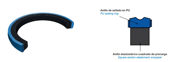
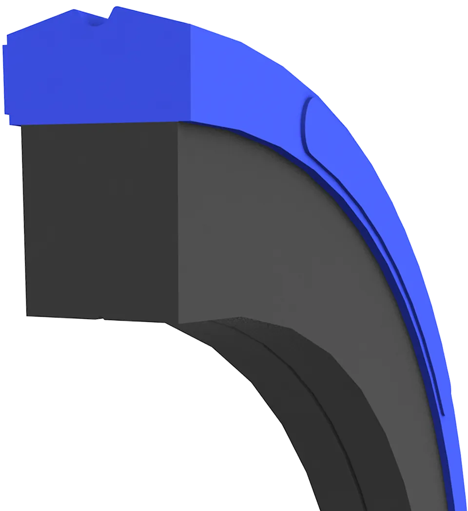
Cette illustration en 3D détaille la structure du joint de piston HPS2. S’agissant d’un joint composite en deux pièces, vous pourrez distinguer la bague d’étanchéité en polyuréthane, de 92 à 95 Shore A, dont la lèvre d’étanchéité prononcée frotte contre la chemise du vérin, et l’élément de pression en NBR logé en dessous, au fond de la gorge. Cet élément ne travaille pas contre la chemise, son rôle est de pousser la lèvre en polyuréthane de façon constante contre la surface de glissement. Sa section est rectangulaire, d’où son comportement anti-torsion, car il ne peut pas tourner dans la gorge comme le ferait un élément à section ronde. La dureté du NBR est choisie selon la taille, 70 Shore A jusqu’à 63 mm de diamètre et 80 Shore A au-delà. L’ensemble assure l’étanchéité dans les deux sens, tient bien aussi bien en statique qu’en dynamique et présente une faible hauteur axiale, ce qui permet des logements réduits. Au montage, l’élément en NBR se place en premier et la bague en polyuréthane ensuite, sans la vriller. Il supporte jusqu’à 40 MPa à des vitesses de glissement pouvant atteindre 0,5 m/s.