| NO | Ød | ØD | b | B | C | R1 |
|---|---|---|---|---|---|---|
| JP-20*12.5*3.2 HPS2 | 12.5 | 20 | 3 | 3.2 | 2 | 0.2 |
| JP-20*14*4.2 HPS2 | 14 | 20 | 4 | 4.2 | 2.5 | 0.3 |
| JP-25*17.5*3.2 HPS2 | 17.5 | 25 | 3 | 3.2 | 2 | 0.2 |
| JP-30*22.5*3.2 HPS2 | 22.5 | 30 | 3 | 3.2 | 2 | 0.2 |
| JP-32*21*4.2 HPS2 | 21 | 32 | 4 | 4.2 | 2.5 | 0.3 |
| JP-32*24.5*3.2 HPS2 | 24.5 | 32 | 3 | 3.2 | 2 | 0.2 |
| JP-40*27*6.3 HPS2 | 27 | 40 | 6 | 6.3 | 3 | 0.3 |
| JP-40*29*4.2 HPS2 | 29 | 40 | 4 | 4.2 | 2.5 | 0.3 |
| JP-40*32.5*3.2 HPS2 | 32.5 | 40 | 3 | 3.2 | 2 | 0.2 |
| JP-45*32*6.3 HPS2 | 32 | 45 | 6 | 6.3 | 3 | 0.3 |
| JP-45*34*4.2 HPS2 | 34 | 45 | 4 | 4.2 | 2.5 | 0.3 |
| JP-50.8*41.4*7.14 HPS2 | 41.4 | 50.8 | 6.85 | 7.14 | 4 | 0.3 |
| JP-50*34.5*6.3 HPS2 | 34.5 | 50 | 6 | 6.3 | 3 | 0.3 |
| JP-50*37*6.3 HPS2 | 37 | 50 | 6 | 6.3 | 3 | 0.3 |
| JP-50*39*4.2 HPS2 | 39 | 50 | 4 | 4.2 | 2.5 | 0.3 |
| JP-55*39.5*6.3 HPS2 | 39.5 | 55 | 6 | 6.3 | 3 | 0.3 |
| JP-60*44.5*6.3 HPS2 | 44.5 | 60 | 6 | 6.3 | 3 | 0.3 |
| JP-60*49*4.2 HPS2 | 49 | 60 | 4 | 4.2 | 2.5 | 0.3 |
| JP-63*47.5*6.3 HPS2 | 47.5 | 63 | 6 | 6.3 | 3 | 0.3 |
| JP-63*50*6.3 HPS2 | 50 | 63 | 6 | 6.3 | 3 | 0.3 |
| JP-63*52*4.2 HPS2 | 52 | 63 | 4 | 4.2 | 2.5 | 0.3 |
| JP-65*49.5*6.3 HPS2 | 49.5 | 65 | 6 | 6.3 | 3 | 0.3 |
| JP-65*52*6.3 HPS2 | 52 | 65 | 6 | 6.3 | 3 | 0.3 |
| JP-65*54*6.3 HPS2 | 54 | 65 | 6 | 6.3 | 4 | 0.3 |
| JP-70*54.5*6.3 HPS2 | 54.5 | 70 | 6 | 6.3 | 4 | 0.3 |
| JP-70*57*6.3 HPS2 | 57 | 70 | 6 | 6.3 | 4 | 0.3 |
| JP-70*59*4.2 HPS2 | 59 | 70 | 4 | 4.2 | 3 | 0.3 |
| JP-75*59.5*6.3 HPS2 | 59.5 | 75 | 6 | 6.3 | 4 | 0.3 |
| JP-75*62*6.3 HPS2 | 62 | 75 | 6 | 6.3 | 4 | 0.3 |
| JP-80*59*8.1 HPS2 | 59 | 80 | 7.75 | 8.1 | 5 | 0.4 |
| JP-80*59*10.5 HPS2 | 59 | 80 | 10 | 10.5 | 7 | 0.4 |
| JP-80*64.5*6.3 HPS2 | 64.5 | 80 | 6 | 6.3 | 4 | 0.3 |
| JP-80*66.5*6.3 HPS2 | 66.5 | 80 | 6 | 6.3 | 4 | 0.3 |
| JP-80*69*4.2 HPS2 | 69 | 80 | 4 | 4.2 | 3 | 0.3 |
| JP-85*69.5*6.3 HPS2 | 69.5 | 85 | 6 | 6.3 | 4 | 0.3 |
| JP-85*71.5*6.3 HPS2 | 71.5 | 85 | 6 | 6.3 | 4 | 0.3 |
| JP-90*69*8.1 HPS2 | 69 | 90 | 7.75 | 8.1 | 5 | 0.4 |
| JP-90*69*10.5 HPS2 | 69 | 90 | 10 | 10.5 | 7 | 0.4 |
| JP-90*74.5*6.3 HPS2 | 74.5 | 90 | 6 | 6.3 | 4 | 0.3 |
| JP-95*79.5*6.3 HPS2 | 79.5 | 95 | 6 | 6.3 | 4 | 0.3 |
| JP-100*79*8.1 HPS2 | 79 | 100 | 7.75 | 8.1 | 5 | 0.4 |
| JP-100*84.5*6.3 HPS2 | 84.5 | 100 | 6 | 6.3 | 4 | 0.3 |
| JP-100*86.5*6.3 HPS2 | 86.5 | 100 | 6 | 6.3 | 4 | 0.3 |
| JP-100*89.5*6.3 HPS2 | 89.5 | 100 | 6 | 6.3 | 4 | 0.3 |
| JP-101.6*92.2*7.14 HPS2 | 92.2 | 101.6 | 6.85 | 7.14 | 4 | 0.3 |
| JP-105*89.5*6.3 HPS2 | 89.5 | 105 | 6 | 6.3 | 4 | 0.3 |
| JP-110*89*8.1 HPS2 | 89 | 110 | 7.75 | 8.1 | 5 | 0.4 |
| JP-110*89*10.5 HPS2 | 89 | 110 | 10 | 10.5 | 7 | 0.4 |
| JP-110*94.5*6.3 HPS2 | 94.5 | 110 | 6 | 6.3 | 4 | 0.3 |
| JP-115*94*8.1 HPS2 | 94 | 115 | 7.75 | 8.1 | 5 | 0.4 |
| JP-120*99*8.1 HPS2 | 99 | 120 | 7.75 | 8.1 | 5 | 0.4 |
| JP-120*99*10.5 HPS2 | 99 | 120 | 10 | 10.5 | 7 | 0.4 |
| JP-120*104.5*6.3 HPS2 | 104.5 | 120 | 6 | 6.3 | 4 | 0.3 |
| JP-125*104*10.5 HPS2 | 104 | 125 | 10 | 10.5 | 7 | 0.4 |
| JP-125*104*8.1 HPS2 | 104 | 125 | 7.75 | 8.1 | 5 | 0.4 |
| JP-125*109.5*6.3 HPS2 | 109.5 | 125 | 6 | 6.3 | 4 | 0.3 |
| JP-130*109*8.1 HPS2 | 109 | 130 | 7.75 | 8.1 | 5 | 0.4 |
| JP-140*119*8.1 HPS2 | 119 | 140 | 7.75 | 8.1 | 5 | 0.4 |
| JP-140*119*10.5 HPS2 | 119 | 140 | 10 | 10.5 | 7 | 0.4 |
| JP-150*129*8.1 HPS2 | 129 | 150 | 7.75 | 8.1 | 5 | 0.4 |
| JP-150*129*10.5 HPS2 | 129 | 150 | 10 | 10.5 | 7 | 0.4 |
| JP-160*139*8.1 HPS2 | 139 | 160 | 7.75 | 8.1 | 5 | 0.4 |
| JP-180*159*8.1 HPS2 | 159 | 180 | 7.75 | 8.1 | 5 | 0.4 |
| JP-200*175*12.5 HPS2 | 175 | 200 | 12 | 12.5 | 9 | 0.4 |
| JP-200*179*8.1 HPS2 | 179 | 200 | 7.75 | 8.1 | 5 | 0.4 |
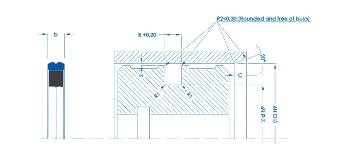
This technical diagram sets out the dimensions and geometric parameters needed to select and install the HPS2 piston seal correctly, a compact two-piece seal consisting of a polyurethane profile ring with a pronounced sealing lip and a rectangular-section NBR pressure element, both housed in the same piston groove to ISO 7425. Two groups of dimensions appear side by side and should not be confused. First the seal’s own dimension, the profile width (b). Then those of the housing, the outside diameter (ØD, to H9), the groove root diameter (Ød, to h9), the groove width (B, to a +0.20 tolerance), the lead-in chamfer length (C) and the groove root radius (R1). The drawing adds the radial clearance between piston and bore (S), the 20° lead-in chamfer angle and the radius of the groove entry edges, R2 < 0.30 mm, which must be rounded and free from burrs. Meeting these dimensions ensures correct pre-load, twist-free installation and stable sealing performance in diameters from 10 to 300 mm.
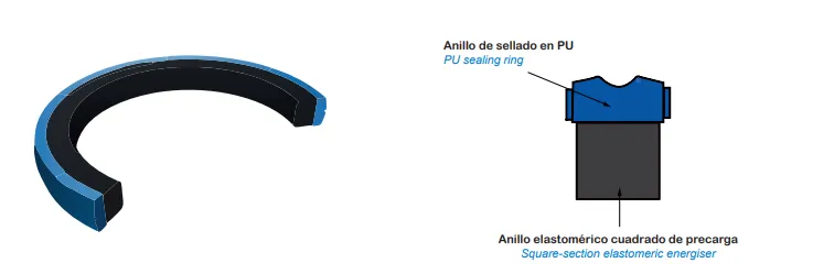
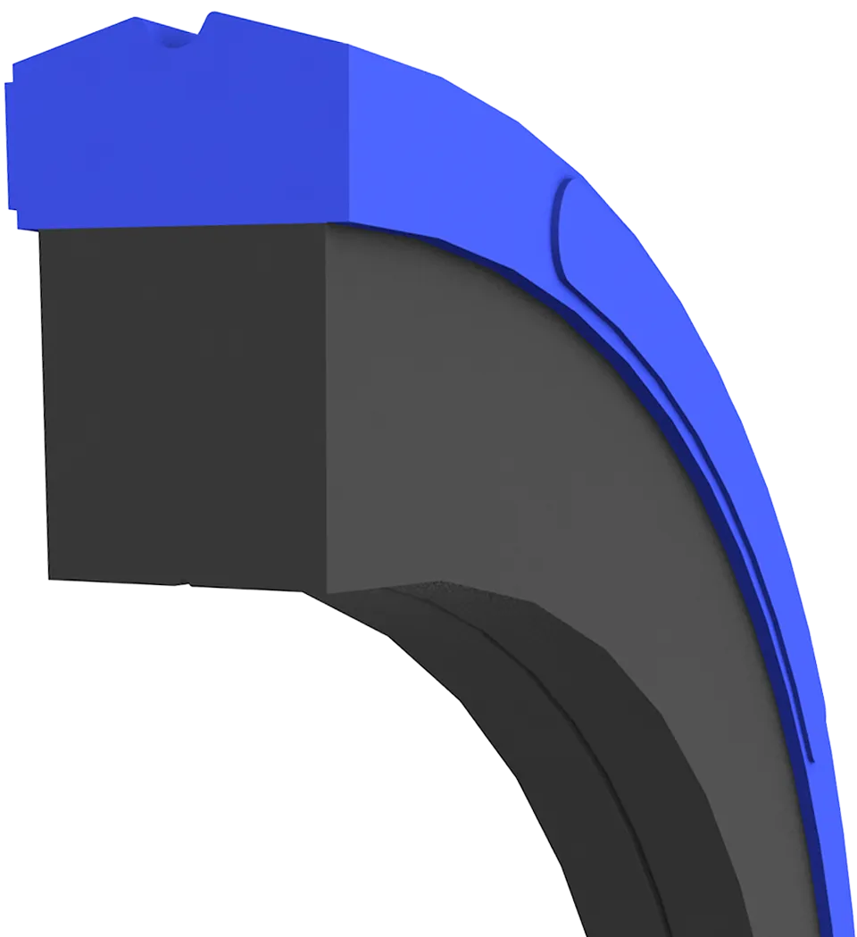
This 3D illustration shows the structure of the HPS2 piston seal. As a two-piece composite seal, it comprises a polyurethane sealing ring at 92 to 95 Shore A, whose pronounced sealing lip runs against the cylinder bore, and an NBR pressure element seated beneath it at the groove root. That element does not run against the bore, its role is to press the polyurethane lip steadily against the sliding surface. Its section is rectangular, which is where its anti-twist behaviour comes from, since it cannot rotate within the groove as a round-section element can. The NBR hardness is chosen by size, 70 Shore A up to 63 mm diameter and 80 Shore A above that. The assembly seals in both directions, holds up well both statically and dynamically and has a low axial height, which allows compact housings. On installation the NBR element goes in first and the polyurethane ring second, without twisting it. It withstands up to 40 MPa at sliding speeds of up to 0.5 m/s.