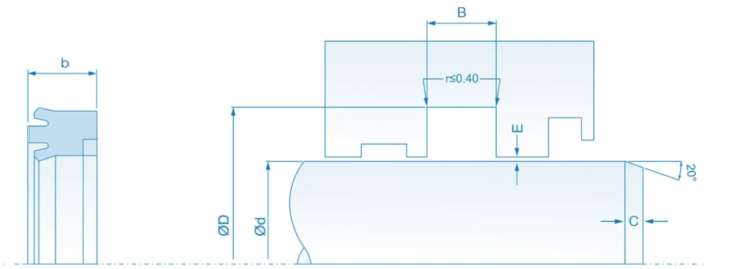
This technical diagram defines the essential dimensions and geometric variables for the correct housing and installation of the UIB2 rod seal. It specifies the critical dimensions from the data tables, including the seal width (b), the groove width (B), the rod inner diameter (Ød) and the housing outer diameter (ØD). It also details the maximum groove bottom radius (r < 0.40 mm), the extrusion gap (E), the length of the lead-in chamfer (C) and its 20° angle. These parameters ensure suitable compression and axial retention of the seal, prevent extrusion failures at high pressures and protect the sealing lips during installation.