Rod seal UIB3

Description
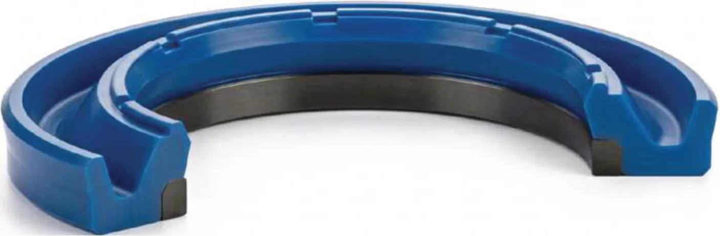
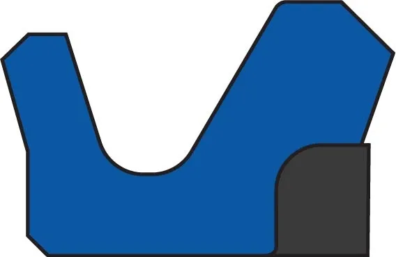
La UIB3 es una junta amortiguadora de vástago que trabaja en tándem con la junta principal como sello primario del sistema. Está formada por un anillo de estanqueidad de poliuretano y un anillo de apoyo termoplástico, y absorbe los picos de presión antes de que lleguen a la junta principal. Su diseño evita que quede presión atrapada entre el sello primario y el secundario, lo que reduce la fricción y protege el conjunto en aplicaciones hidráulicas exigentes.
Assembly
Montar en ranura cerrada según ISO 7425/2 y las medidas de la ficha, siempre en tándem con la junta principal de vástago. Limpiar bien el alojamiento, achaflanar y redondear los cantos vivos y no arrastrar la junta sobre aristas cortantes. Lubricar el vástago antes del montaje para facilitar la colocación y proteger el anillo.
Advantages
Materials
Fabricada en POLIURETANO de 95 Shore A para el anillo de estanqueidad y POM de 60 Shore D para el anillo de apoyo. Esta combinación ofrece alta resistencia al desgaste y a la extrusión frente a picos de presión, y es compatible con aceites hidráulicos minerales y grasas. Para fluidos ignífugos HFA, HFB y HFC conviene confirmar la compatibilidad y los rangos de temperatura según el compuesto.
Technical data
ALP NODIMENSIONØdØDbBCR1
A209-036 PU36~46.7~4.23646.73.94.250.2
A209-038 PU38~48.7~4.23848.73.94.250.2
A209-040 PU40~55.5~6.34055.566.360.2
A209-045 PU45~60.5~6.34560.566.360.2
A209-050 PU50~65.5~6.35065.566.360.2
A209-055 PU55~70.5~6.35570.566.350.2
A209-055/1 PU55~65.7~4.25565.73.94.260.2
A209-060 PU60~75.5~6.36075.566.360.2
A209-063 PU63~78.5~6.36378.566.360.2
A209-065 PU65~80.5~6.36580.566.360.2
A209-070 PU70~85.5~6.37085.566.360.2
A209-075 PU75~90.5~6.37590.566.360.2
A209-080 PU80~95.5~6.38095.566.360.2
A209-085 PU85~100.5~6.385100.566.360.2
A209-090 PU90~105.5~6.390105.566.360.2
A209-095 PU95~110.5~6.395110.566.360.2
A209-100 PU100~115.5~6.3100115.566.360.2
A209-105 PU105~120.5~6.3105120.566.360.2
A209-110 PU110~125.5~6.3110125.566.360.2
A209-115 PU115~130.5~6.3115130.566.360.2
A209-120 PU120~135.5~6.3120135.566.360.2
A209-125 PU125~140.5~6.3125140.566.360.2
A209-130 PU130~145.5~6.3130145.566.360.2
A209-140 PU140~155.5~6.3140155.566.360.2
A209-150 PU150~165.5~6.3150165.566.360.2
A209-160 PU160~175.5~6.3160175.566.360.2
A209-170 PU170~185.5~6.3170185.566.360.2
A209-180 PU180~195.5~6.3180195.566.360.2
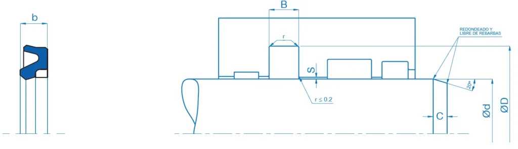
Technical drawing and installation parameters of the UIB3 rod seal
This technical diagram defines the essential dimensions and geometric variables for the correct housing and installation of the UIB3 rod seal. It specifies the critical dimensions linked to the data tables, including the seal width (b), the groove width (B), the rod inner diameter (Ød) and the housing outer diameter (ØD). It also details the geometric specifications of the bottom and edge radii (r and r1), the extrusion gap (E), as well as the length (C) and the 20° angle of the lead-in chamfer (rounded and free of burrs). These values ensure perfect alignment, prevent pinching or damage to the sealing lips during installation and guarantee efficient, long-lasting sealing under demanding pressure conditions.
Three-dimensional view and components of the UIB3 rod seal
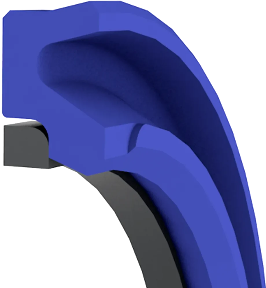
This 3D illustration details the basic structure of the UIB3 single-acting rod seal for hydraulic applications. The diagram clearly shows its key elements and features: the polyurethane body, the asymmetrical sealing lips (with the shortened inner lip and sealing edge) and the integrated back-up ring. This configuration extends the working range against high pressures and extrusion gaps, guaranteeing optimum static and dynamic sealing performance together with effective protection against dirt.
Contacto OSN

Can we help you?

Our team will help you find the best solution and choose the optimal profile and material for your application.
Customer Area
Access for registered distributors and industrial suppliers.
E-shop
Direct purchase, with or without an account.