Rod seal UIR2

Description
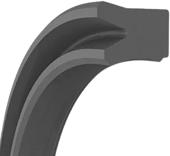
Asymmetrical single-acting hydraulic rod seal with a U-shaped profile and a secondary sealing lip that backs up the main lip. The main lip seals the rod using system pressure, while the secondary lip improves lubrication, wipes off oil traces on every stroke and keeps dirt out. Its high abrasion resistance gives a long service life. UIR2 is designed for standardised housings and demanding duties.
Assembly
The UIR2 is fitted into a closed groove. Chamfer the edges of the housing and the rod to prevent damage, and clean the installation space before assembly. Do not pull the seal over sharp edges, threads or keyways: use a mounting sleeve if necessary. Oil the rod before installing the assembly to ensure a correct seal.
Advantages
Materials
Available in NBR, EPDM, FKM, FFKM, NR, CR, VMQ and PTFE materials, selectable according to the working fluid and temperature. This range offers an optimal combination of chemical resistance and thermal stability, with good behaviour against hydraulic oils, lubricating oils, greases and flame-retardant fluids HFA, HFB and HFC. Choosing the right compound ensures reliable sealing and a long rod service life.
Technical data
NO.ØdØDbBC
U-22*28*4.5 UIR222284.553
U-28*36*5.3 UIR228365.36.33
U-40*50*10 UIR2405010114
U-40*55*10 UIR2405510115
U-40*48*5.3 UIR240485.36.33
U-45*55*7 UIR24555784
U-50*62*8.6 UIR250628.69.64.5
U-50*60*7 UIR25060784
U-50*60*10 UIR2506010114
U-50*65*10 UIR2506510115
U-50*62*8 UIR25062894.5
U-60*70*12.5 UIR2607012.513.54
U-60*70*12 UIR2607012134
U-65*80*11.5 UIR2658011.512.55
U-65*75*7 UIR26575784
U-70*80*7 UIR27080784
U-80*90*7 UIR28090784
U-100*113*12.5 UIR210011312.513.54.5
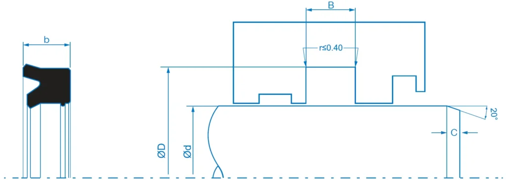
Technical drawing and installation parameters of the UIR2 rod seal
This technical diagram defines the essential dimensions and geometric variables for the correct housing and installation of the UIR2 rod seal. It specifies the critical dimensions linked to the specification tables, such as the seal width (b), the groove width (B), the rod inner diameter (Ød) and the housing outer diameter (ØD). It also details the maximum groove bottom radius (r < 0.40 mm), the length of the lead-in chamfer (C) and its 20° angle. These parameters ensure correct positioning of the secondary lip to optimise lubrication on every stroke, prevent the ingress of dirt and avoid pinching or premature wear during installation in standardised housings.
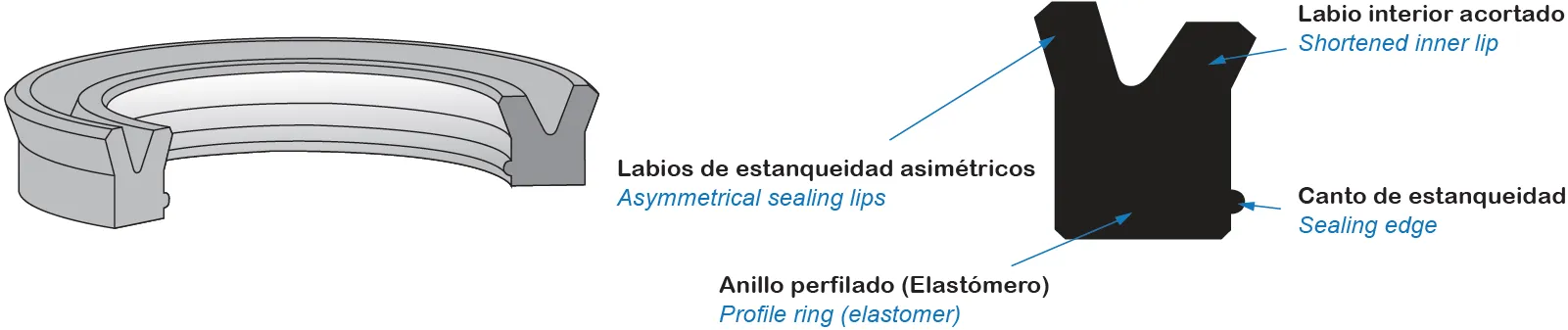
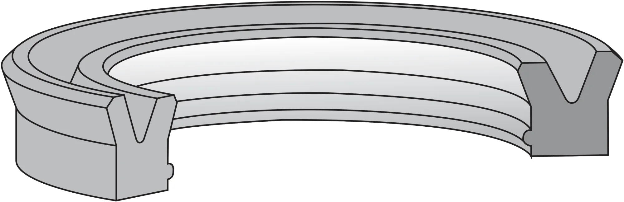
Three-dimensional view and components of the UIR2 rod seal
This 3D illustration details the basic structure of the UIR2 hydraulic rod seal. The diagram shows its key elements: the profiled elastomer ring with an asymmetrical U-profile, the shortened inner lip and the additional sealing edge/secondary lip. This configuration allows the main lip to seal effectively with the system pressure, while the secondary lip improves lubrication, wipes the oil traces on every stroke and acts as a barrier against the ingress of dirt.
Contacto OSN

Can we help you?

Our team will help you find the best solution and choose the optimal profile and material for your application.
Customer Area
Access for registered distributors and industrial suppliers.
E-shop
Direct purchase, with or without an account.