| NO | Ød | ØD | B | C | Ød1 |
|---|---|---|---|---|---|
| U-20*10*8.9 CP | 10 | 20 | 9.3 | 6 | 19.5 |
| U-22*12*8.9 CP | 12 | 22 | 9.3 | 6 | 21.5 |
| U-25*15*8.9 CP | 15 | 25 | 9.3 | 6 | 24.5 |
| U-28*18*8.9 CP | 18 | 28 | 9.3 | 6 | 27.5 |
| U-30*20*8.9 CP | 20 | 30 | 9.3 | 6 | 29.5 |
| U-32*20*10.4 CP | 20 | 32 | 10.9 | 6 | 31 |
| U-35*23*10.4 CP | 23 | 35 | 10.9 | 6 | 34 |
| U-36*24*10.4 CP | 24 | 36 | 10.9 | 6 | 35 |
| U-40*25*11 CP | 25 | 40 | 11.5 | 6 | 39 |
| U-42*27*11 CP | 27 | 42 | 11.5 | 6 | 41 |
| U-45*30*11 CP | 30 | 45 | 11.5 | 6 | 44 |
| U-50*35*11 CP | 35 | 50 | 11.5 | 6 | 49 |
| U-55*40*11 CP | 40 | 55 | 11.5 | 6 | 54 |
| U-56*41*11 CP | 41 | 56 | 11.5 | 6 | 55 |
| U-60*45*11 CP | 45 | 60 | 11.5 | 6 | 59 |
| U-63*48*12.5 CP | 48 | 63 | 13 | 6 | 62 |
| U-70*50*14.6 CP | 50 | 70 | 15.2 | 7 | 69 |
| U-80*60*14.6 CP | 60 | 80 | 15.2 | 7 | 79 |
| U-90*70*20.6 CP | 70 | 90 | 21.2 | 7 | 89 |
| U-100*80*20.6 CP | 80 | 100 | 21.2 | 7 | 99 |
| U-110*90*20.6 CP | 90 | 110 | 21.2 | 7 | 109 |
| U-115*95*20.6 CP | 95 | 115 | 21.2 | 7 | 114 |
| U-125*100*25 CP | 100 | 125 | 25.8 | 8 | 124 |
| U-140*115*25 CP | 115 | 140 | 25.8 | 8 | 139 |
| U-150*120*28 CP | 120 | 150 | 29 | 8 | 148.5 |
| U-160*130*28 CP | 130 | 160 | 29 | 8 | 158.5 |
| U-180*150*30.5 CP | 150 | 180 | 31.5 | 8 | 178.5 |
| U-200*170*32.5 CP | 170 | 200 | 33.5 | 8 | 198.5 |
| U-250*220*32.5 CP | 220 | 250 | 33.5 | 8 | 248.5 |
| U-300*270*32.5 CP | 270 | 300 | 33.5 | 8 | 299.5 |
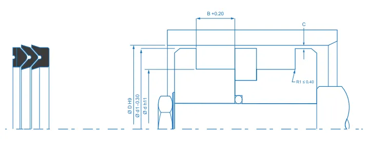
This technical diagram sets out the dimensions and geometric parameters needed to select and install the CP piston seal correctly, a single-acting V-profile sealing set made up of a pressure ring, one or more sealing rings and a support ring, all stacked in the same piston groove. It shows the dimensions linked to the size table, the outside diameter (ØD, to H9), the groove root diameter (Ød, to h11), the intermediate diameter (Ød1, to -0.30), the groove width (B, to a +0.20 tolerance) and the lead-in chamfer length (C). The drawing adds the fillet radius, R1 ≤ 0.40 mm. It is worth noting that the groove width does not match the third figure of the reference, which is the height of the stacked set, the groove is always slightly wider to leave room for assembly clearance. The housing must be left clean, with radiused edges and free from burrs, and meeting these dimensions ensures correct stacking, even pressure distribution and stable performance in diameters from 10 to 500 mm.
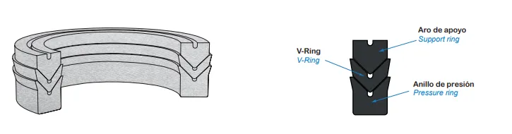
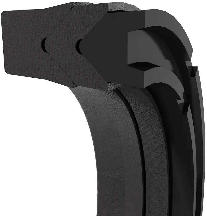
This 3D illustration shows the structure of the CP piston seal. It is not a single part but a stacked set of three kinds of element. The pressure ring sits on the pressure side and transmits the load to the rest of the set. The V-rings do the sealing, and one or more can be fitted according to pressure and duty, which is what allows the configuration to be adapted to each application. The support ring closes the set on the side away from the pressure and acts as its seat. The lips must face the pressure. This division of duties gives the profile its performance, the NBR or FKM impregnated cotton fabric takes high pressures and works well even on worn or irregular surfaces, the stack spreads the load evenly and the set compensates for misalignment and for clearances between sealing elements. The rings are made in NBR or FKM at 85 Shore A, with an elastomeric assembly hardness of 75 to 85 Shore A, and the support ring can also be supplied in POM at 60 Shore D. It withstands up to 40 MPa at sliding speeds of up to 0.5 m/s.