| NO | Ød | ØD | b | B | C | Ød1 |
|---|---|---|---|---|---|---|
| U-16*10*3 COP | 10 | 16 | 3 | 3.5 | 4 | 15 |
| U-24*18*4 COP | 18 | 24 | 4 | 4.5 | 4 | 23 |
| U-25*19*3.25 COP | 19 | 25 | 3.25 | 3.75 | 4 | 24 |
| U-32*24*5.5 COP | 24 | 32 | 5.5 | 6 | 5 | 30.5 |
| U-40*30*7 COP | 30 | 40 | 7 | 7.5 | 6 | 38.5 |
| U-42*30*10 COP | 30 | 42 | 10 | 11 | 6 | 40.5 |
| U-50*40*7 COP | 40 | 50 | 7 | 7.5 | 6 | 48.5 |
| U-50*36*7 COP | 36 | 50 | 7 | 7.5 | 6 | 48.5 |
| U-60*48*6.5 COP | 48 | 60 | 6.5 | 7 | 6 | 58.5 |
| U-63*53*7 COP | 53 | 63 | 7 | 7.5 | 6 | 61.5 |
| U-80*68*8.5 COP | 68 | 80 | 8.5 | 9.5 | 6 | 78.5 |
| U-100*88*8.5 COP | 88 | 100 | 8.5 | 9.5 | 6 | 98 |
| U-125*110*10 COP | 110 | 125 | 10 | 11 | 6.5 | 123 |
| U-125*105*8.25 COP | 105 | 125 | 8.25 | 9.25 | 8 | 123 |
| U-160*140*14 COP | 140 | 160 | 14 | 15 | 8 | 158 |
| U-160*140*8.25 COP | 140 | 160 | 8.25 | 9.25 | 8 | 158 |
| U-160*145*10 COP | 145 | 160 | 10 | 11 | 7 | 158 |
| U-180*160*12 COP | 160 | 180 | 12 | 13 | 8 | 178 |
| U-200*180*14 COP | 180 | 200 | 14 | 15 | 8 | 198 |
| U-250*226*16 COP | 226 | 250 | 16 | 17 | 8 | 248 |
| U-250*230*14 COP | 230 | 250 | 14 | 15 | 8 | 248 |
| U-320*295*17 COP | 295 | 320 | 17 | 18 | 11 | 317 |
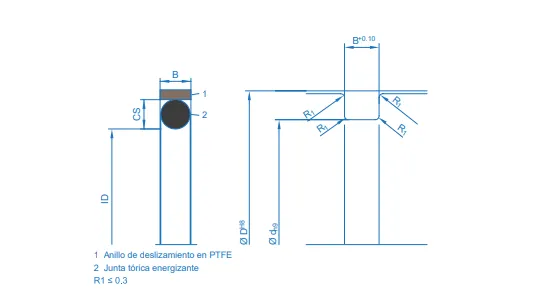
This technical diagram sets out the dimensions and geometric parameters needed to select and install the HPO piston seal correctly, a two-piece profile consisting of a PTFE slide ring and an energising O-ring, both housed in the piston groove. It shows the dimensions linked to the size table, the outside diameter (ØD), the groove root diameter (Ød) and the groove width (B), together with the two dimensions of the O-ring itself, its cord section (CS) and its inside diameter (ID). The groove is machined with the outside diameter to H8, the root to h9 and the width to a +0.10 tolerance, and its edges must be radiused to R1 ≤ 0.3 mm and left free from burrs. Meeting these dimensions ensures correct O-ring pre-load, twist-free installation and stable sealing performance in diameters from 10 to 2500 mm.
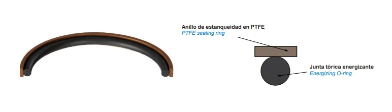
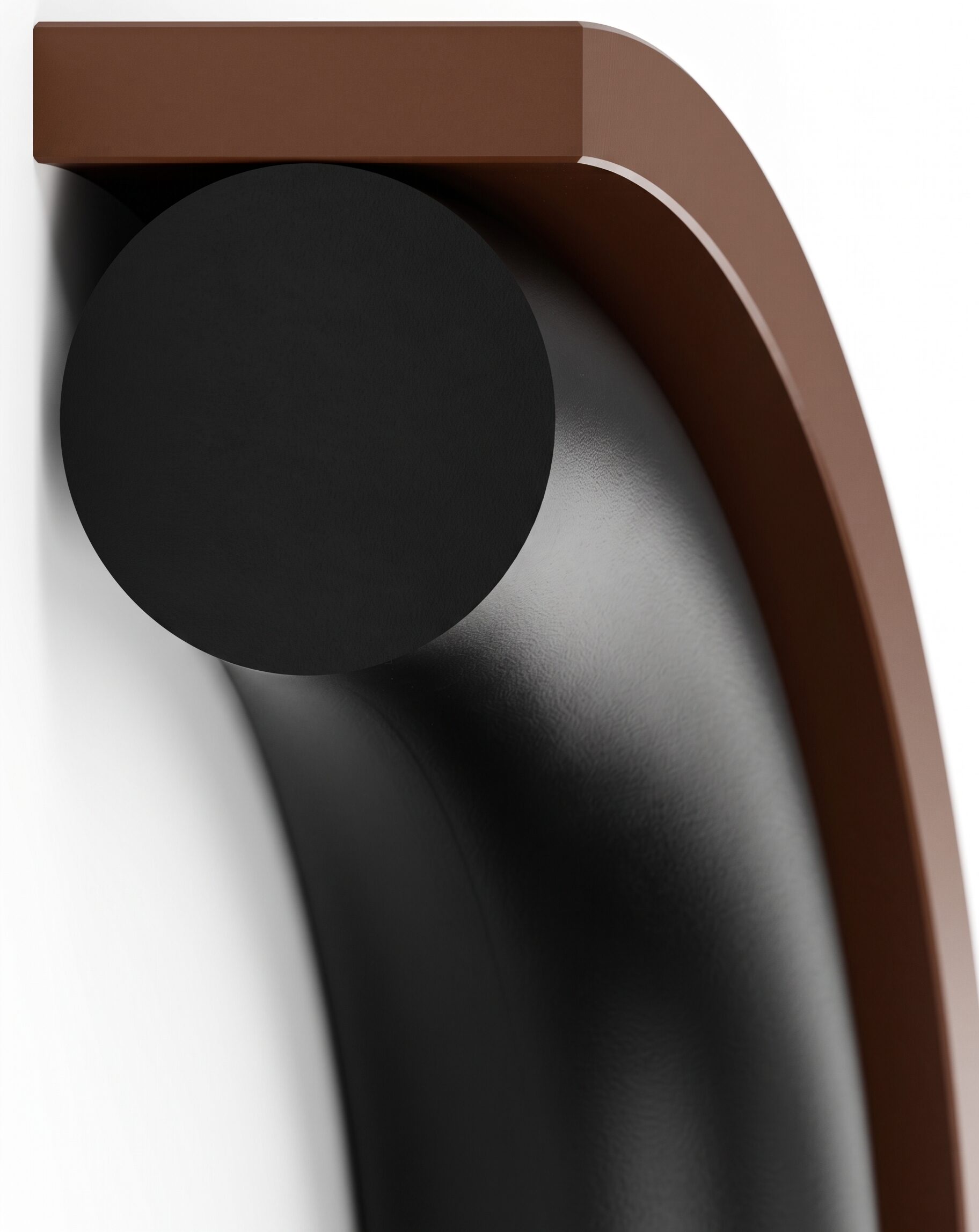
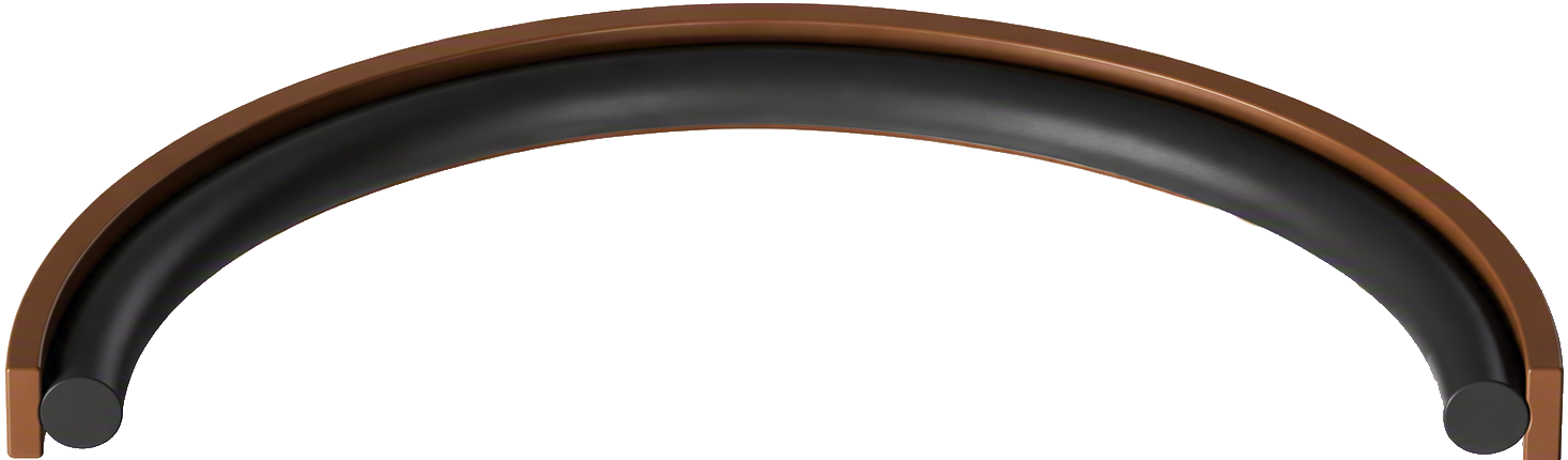
This 3D illustration shows the structure of the HPO piston seal. As a two-piece profile, it comprises a bronze-filled PTFE sealing ring at 60 Shore D, which runs against the cylinder bore, and an energising O-ring in NBR or FKM at 70 to 80 Shore A, seated beneath it at the groove root. The O-ring does not run against the bore, its role is to press the PTFE ring steadily against the sliding surface and to compensate for wear and for temperature variation. This division of duties gives the profile its two strengths, the PTFE provides low friction, freedom from stick-slip and high wear resistance, and the elastomer provides the closing force required even at low pressure. The assembly seals in both directions and withstands up to 35 MPa at speeds of up to 1.5 m/s.