| NO | ØD | Ød | H | Ø d1 | L1 | L2 | L3 | R1 | R2 |
|---|---|---|---|---|---|---|---|---|---|
| JP-16*10*10.5 DRW | 16 | 10 | 10.5 | 13.5 | 12 | 3 | 4.5 | 0.9 | 0.2 |
| JP-18*12*10.5 DRW | 18 | 12 | 10.5 | 15.5 | 12 | 3 | 4.5 | 0.9 | 0.2 |
| JP-20*14*10.5 DRW | 20 | 14 | 10.5 | 17.5 | 12 | 3 | 4.5 | 0.9 | 0.2 |
| JP-25*18*12 DRW | 25 | 18 | 12 | 22.5 | 13 | 3 | 5 | 1.3 | 0.2 |
| JP-28*22*10.5 DRW | 28 | 22 | 10.5 | 25.5 | 12 | 3 | 4.5 | 0.9 | 0.2 |
| JP-30*23*12 DRW | 30 | 23 | 12 | 27.5 | 13 | 3 | 5 | 1.3 | 0.2 |
| JP-32*25*12 DRW | 32 | 25 | 12 | 29.5 | 13 | 3 | 5 | 1.3 | 0.2 |
| JP-35*28*12 DRW | 35 | 28 | 12 | 32.5 | 13 | 3 | 5 | 1.3 | 0.2 |
| JP-40*33*12 DRW | 40 | 33 | 12 | 37.5 | 13 | 3 | 5 | 1.3 | 0.2 |
| JP-45*38*12 DRW | 45 | 38 | 12 | 42.5 | 13 | 3 | 5 | 1.3 | 0.2 |
| JP-50*43*12 DRW | 50 | 43 | 12 | 47.5 | 13 | 3 | 5 | 1.3 | 0.2 |
| JP-54*46*13 DRW | 54 | 46 | 13 | 51.5 | 15 | 4 | 5.5 | 1.3 | 0.2 |
| JP-63*53*17 DRW | 63 | 53 | 17 | 60 | 19 | 5 | 7 | 1.6 | 0.3 |
| JP-63*56*12 DRW | 63 | 56 | 12 | 60.5 | 13 | 3 | 5 | 1.3 | 0.3 |
| JP-70*62*13 DRW | 70 | 62 | 13 | 67.5 | 15 | 4 | 5.5 | 1.6 | 0.3 |
| JP-76*66*18 DRW | 76 | 66 | 18 | 73 | 20 | 6 | 7 | 1.6 | 0.3 |
| JP-80*72*13 DRW | 80 | 72 | 13 | 77.4 | 15 | 4 | 5.5 | 1.6 | 0.3 |
| JP-80*70*18 DRW | 80 | 70 | 18 | 77 | 20 | 6 | 7 | 1.6 | 0.3 |
| JP-100*88*21 DRW | 100 | 88 | 21 | 96.5 | 23 | 8 | 7.5 | 1.6 | 0.4 |
| JP-100*90*16 DRW | 100 | 90 | 16 | 97 | 18 | 4 | 7 | 1.6 | 0.3 |
| JP-125*113*15 DRW | 125 | 113 | 15 | 122 | 17 | 5 | 6 | 1.6 | 0.4 |
| JP-125*113*21 DRW | 125 | 113 | 21 | 121.5 | 23 | 8 | 7.5 | 1.6 | 0.4 |
| JP-130*120*17 DRW | 130 | 120 | 17 | 127 | 19 | 5 | 7 | 1.6 | 0.3 |
| JP-140*128*21 DRW | 140 | 128 | 21 | 136.5 | 23 | 8 | 7.5 | 1.6 | 0.4 |
| JP-150*140*17 DRW | 150 | 140 | 17 | 147 | 19 | 5 | 7 | 1.6 | 0.3 |
| JP-160*145*26 DRW | 160 | 145 | 26 | 155.5 | 29 | 10 | 9.5 | 1.6 | 0.4 |
| JP-200*185*26 DRW | 200 | 185 | 26 | 195.5 | 29 | 10 | 9.5 | 1.6 | 0.4 |
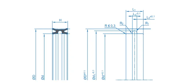
This technical diagram sets out the dimensions and geometric parameters needed to select and install the DRW piston seal correctly, a double-lip pneumatic seal with asymmetric geometry fitted on a one-piece piston. Two groups of dimensions appear side by side and should not be confused. First those of the seal itself, the outside diameter (ØD), the inside diameter (Ød) and the profile height (H). Then those of the piston, the bore diameter (ØD to H11), the two piston diameters (Ød1 to -0.1 and Ød to +0.1), the three axial dimensions (L1, L2 to -0.1 and L3 to ±0.1) and the fillet radii R1 and R2, plus the general edge radius, R ≤ 0.3. The nine dimensions on the drawing are exactly the nine columns of the size table. The piston must be left free from sharp edges, and meeting these dimensions ensures that both lips bear correctly, that the guide surface does its job and that installation is twist-free, in diameters from 10 to 300 mm.
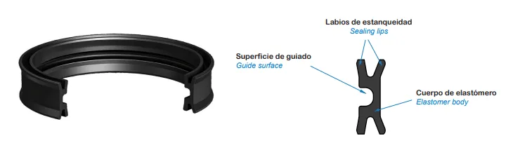
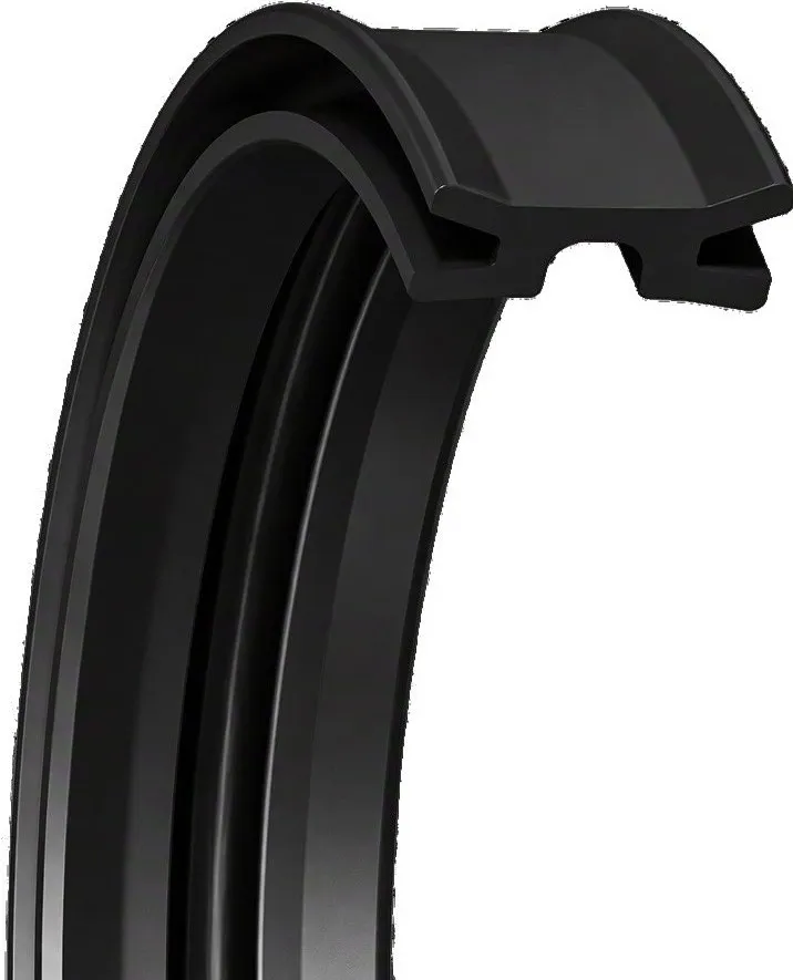
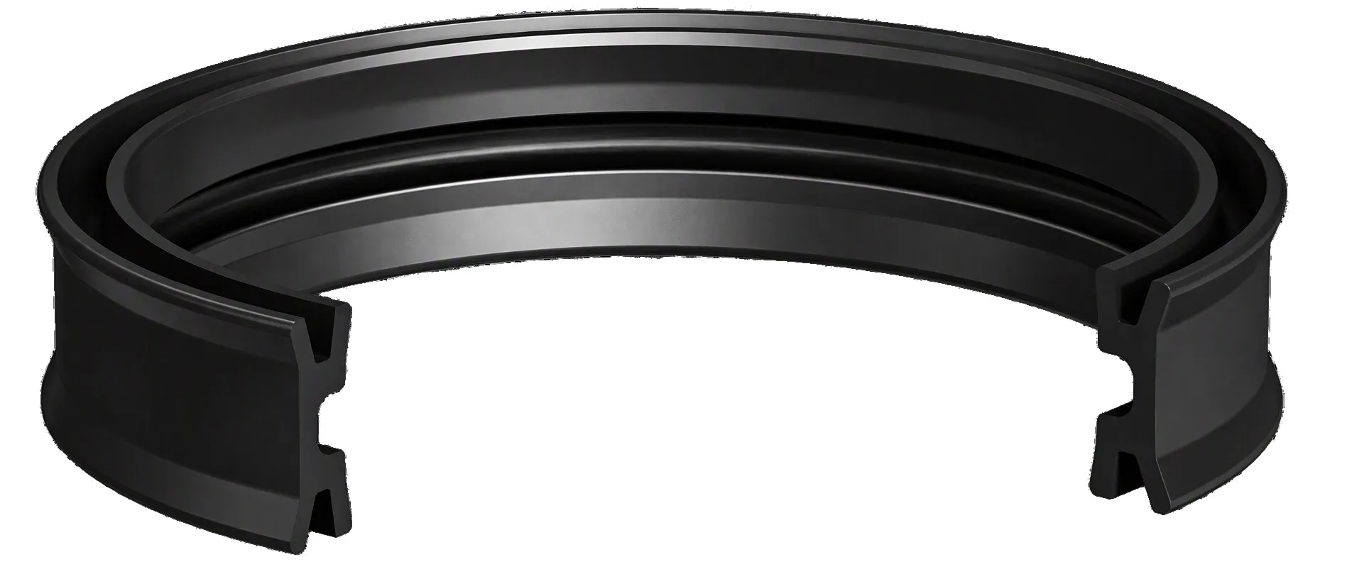
This 3D illustration shows the structure of the DRW piston seal. Unlike composite profiles, this is a single elastomer part in which three areas do different jobs. The two sealing lips close against the cylinder bore. The guide surface, built into the body itself, bears on the bore, steadies the piston and prevents metal-to-metal contact, so no separate guide ring is needed. The elastomer body joins the two and gives the profile its asymmetric geometry, which means the seal has a defined orientation that must be respected on fitting. With no auxiliary parts, installation on one-piece pistons is straightforward, it is enough to lubricate the seal and the housing lightly and to avoid sharp edges. The standard material is NBR at 70 to 80 Shore A, and FKM at 80 Shore A for elevated temperatures. It withstands sliding speeds of up to 0.5 m/s with compressed air, lubricated or not, after the initial lubrication on assembly.