| NO | Ød (h9) | ØD (H9) | B (+0.2) | C | r |
|---|---|---|---|---|---|
| JP-40*30*8 HOD | 30 | 40 | 8 | 5 | 0.3 |
| JP-50*36*9 HOD | 36 | 50 | 9 | 6.5 | 0.3 |
| JP-55*41*9 HOD | 41 | 55 | 9 | 6.5 | 0.3 |
| JP-60*46*9 HOD | 46 | 60 | 9 | 6.5 | 0.3 |
| JP-60*50*8 HOD | 50 | 60 | 8 | 5 | 0.3 |
| JP-63*48*11 HOD | 48 | 63 | 11 | 7.5 | 0.5 |
| JP-63*53*8 HOD | 53 | 63 | 8 | 5 | 0.3 |
| JP-65*50*11 HOD | 50 | 65 | 11 | 7.5 | 0.5 |
| JP-70*55*11 HOD | 55 | 70 | 11 | 7.5 | 0.5 |
| JP-75*60*11 HOD | 60 | 75 | 11 | 7.5 | 0.5 |
| JP-80*65*11 HOD | 65 | 80 | 11 | 7.5 | 0.5 |
| JP-80*70*11 HOD | 70 | 80 | 11 | 7.5 | 0.5 |
| JP-85*70*11 HOD | 70 | 85 | 11 | 7.5 | 0.5 |
| JP-90*75*11 HOD | 75 | 90 | 11 | 7.5 | 0.5 |
| JP-95*80*11 HOD | 80 | 95 | 11 | 7.5 | 0.5 |
| JP-100*85*12.5 HOD | 85 | 100 | 12.5 | 7.5 | 0.5 |
| JP-105*88*14 HOD | 88 | 105 | 14 | 8.5 | 0.5 |
| JP-105*90*12.5 HOD | 90 | 105 | 12.5 | 7.5 | 0.5 |
| JP-105*90*13.5 HOD | 90 | 105 | 13.5 | 7.5 | 0.5 |
| JP-110*95*12.5 HOD | 95 | 110 | 12.5 | 7.5 | 0.5 |
| JP-115*100*12.5 HOD | 100 | 115 | 12.5 | 7.5 | 0.5 |
| JP-120*105*12.5 HOD | 105 | 120 | 12.5 | 7.5 | 0.6 |
| JP-125*102*16 HOD | 102 | 125 | 16 | 11.5 | 0.6 |
| JP-130*107*16 HOD | 107 | 130 | 16 | 11.5 | 0.6 |
| JP-135*112*16 HOD | 112 | 135 | 16 | 11.5 | 0.6 |
| JP-140*117*16 HOD | 117 | 140 | 16 | 11.5 | 0.6 |
| JP-145*122*16 HOD | 122 | 145 | 16 | 11.5 | 0.6 |
| JP-150*127*16 HOD | 127 | 150 | 16 | 11.5 | 0.6 |
| JP-160*137*16 HOD | 137 | 160 | 16 | 11.5 | 0.6 |
| JP-165*145*17 HOD | 145 | 165 | 17 | 10.5 | 0.6 |
| JP-170*147*16 HOD | 147 | 170 | 16 | 11.5 | 0.6 |
| JP-170*155*16 HOD | 155 | 170 | 16 | 7.5 | 0.6 |
| JP-180*157*16 HOD | 157 | 180 | 16 | 11.5 | 0.6 |
| JP-180*160*18 HOD | 160 | 180 | 18 | 10.5 | 0.6 |
| JP-190*167*16 HOD | 167 | 190 | 16 | 11.5 | 0.6 |
| JP-200*177*16 HOD | 177 | 200 | 16 | 11.5 | 0.6 |
| JP-210*187*16 HOD | 187 | 210 | 16 | 11.5 | 0.6 |
| JP-220*197*16 HOD | 197 | 220 | 16 | 11.5 | 0.6 |
| JP-220*200*16 HOD | 200 | 220 | 16 | 10.5 | 0.6 |
| JP-225*202*16 HOD | 202 | 225 | 16 | 11.5 | 0.6 |
| JP-250*222*17.5 HOD | 222 | 250 | 17.5 | 14 | 0.6 |
| JP-250*227*16 HOD | 227 | 250 | 16 | 11.5 | 0.6 |
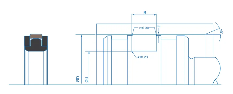
This technical diagram sets out the dimensions and geometric parameters needed to select and install the HOD piston seal correctly, a heavy-duty assembly consisting of a PTFE sealing ring, an elastomer energiser and two bearing rings, all housed in the same piston groove. It shows the dimensions linked to the size table, the outside diameter (ØD, to H9), the groove root diameter (Ød, to h9) and the groove width (B, to a +0.2 tolerance), together with the radial clearance between piston and bore (E), which governs the risk of extrusion as pressure rises. The groove entry edges are radiused to r ≤ 0.30 mm and the root to r ≤ 0.20 mm, and the piston is finished with a 20° lead-in chamfer, whose length is given in column C of the table. The surfaces must be left free from porosity, scoring and sharp edges, and meeting these dimensions ensures correct pre-load, twist-free installation and stable sealing performance in diameters from 10 to 300 mm.
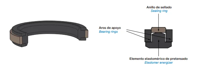
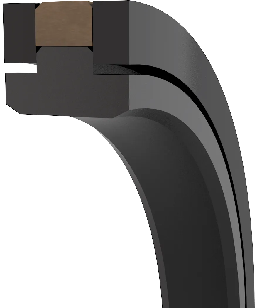
This 3D illustration shows the structure of the HOD piston seal. Unlike two-piece profiles, three elements work together here, each with its own job. The bronze-filled PTFE sealing ring runs against the cylinder bore and determines friction and wear resistance. The elastomer energiser, in NBR at 80 Shore A, sits beneath it and holds the PTFE ring steadily against the sliding surface while absorbing pressure peaks. The bearing rings, in POM or polyamide, sit on either side of the assembly, guide it within the groove and stop it extruding through the clearance as pressure rises, which is what allows the 50 MPa rating. For high temperatures the energiser is made in FKM and the bearing rings in virgin PTFE. The assembly seals in both directions and withstands sliding speeds of up to 1.5 m/s.