| NO | Ød | ØD | L | E | r |
|---|---|---|---|---|---|
| JP-70*55*7.5 HPS | 55 | 70 | 7.5 | 4 | 0.3 |
| JP-75*60*7.5 HPS | 60 | 75 | 7.5 | 4 | 0.3 |
| JP-80*65*7.5 HPS | 65 | 80 | 7.5 | 4 | 0.3 |
| JP-90*75*7.5 HPS | 75 | 90 | 7.5 | 4 | 0.3 |
| JP-100*85*7.5 HPS | 85 | 100 | 7.5 | 4 | 0.3 |
| JP-140*122*8 HPS | 122 | 140 | 8 | 5 | 0.4 |
| JP-150*132*8 HPS | 132 | 150 | 8 | 5 | 0.4 |
| JP-160*140*9 HPS | 140 | 160 | 9 | 5 | 0.4 |
| JP-170*150*9 HPS | 150 | 170 | 9 | 5 | 0.4 |
| JP-190*168*10 HPS | 168 | 190 | 10 | 5 | 0.4 |
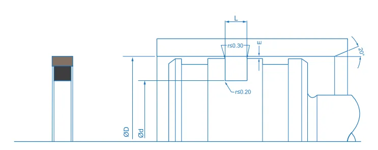
This technical diagram sets out the dimensions and geometric parameters needed to select and install the HPS piston seal correctly, a two-piece composite seal consisting of a PTFE slide ring and a square-section elastomeric energiser, both housed in the same piston groove. It shows the dimensions linked to the size table, the outside diameter (ØD), the groove root diameter (Ød), the groove width (L) and the radial clearance between piston and bore (E), which governs the risk of extrusion as pressure rises. The groove entry edges are radiused to r ≤ 0.30 mm, the value given in the table, and the root to r ≤ 0.20 mm, and the piston is finished with a 20° lead-in chamfer. The groove must be left clean, deburred and free from sharp edges, and meeting these dimensions ensures correct pre-load, twist-free installation and stable sealing performance in diameters from 10 to 300 mm.
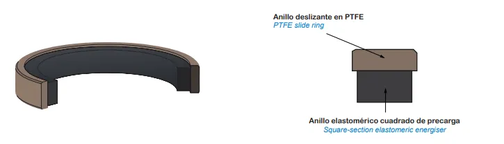
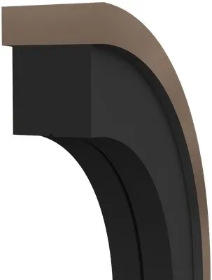
This 3D illustration shows the structure of the HPS piston seal. As a two-piece composite seal, it comprises a bronze-filled or glass-filled PTFE slide ring, which runs against the cylinder bore, and a square-section elastomeric energiser in NBR or FKM at 70 to 75 Shore A, seated beneath it at the groove root. What sets this profile apart from others in the range is the section of the energiser, square here rather than round. That shape spreads the support over a larger area, stabilises the PTFE ring and allows larger extrusion gaps than many conventional PTFE or polyurethane seals will accept. The PTFE provides low friction, good thermal conductivity and resistance to wear, abrasion and pressure shocks, and the elastomer provides the closing force required even at low pressure. On installation the energiser goes in first and the PTFE ring second. The assembly seals in both directions and withstands up to 35 MPa at speeds of up to 1.5 m/s.